


I write this as asked a few questions about my name on the Elecraft UK builders list.... http://www.elecraft.com/k2_builders.htm
I don't get paid by them to build for anyone and I don't pay them to include me on the list.
Exchange with one amateur from UK and I am building his K1 right now:
> I hope you don't mind me asing... I wonder how much you charge for your services? I am just in the process of buying a K1-4 and unfortunately just do not have the ability to build kits anymore due to a disability just don’t have the feeling in my fingers anymore since an accident last year).
My response:
Don't mind at all.
Yes I do build some things for others including now being asked to build Elecraft kits. Right now shack is insulated (and now heated so maybe less vfo drift!) with power etc. I have an IQPro DDS near completion, a PIC-A-STAR and a 500KHz TX needs finished off. I have just finished a number of softrock SDR builds but I only tend to work on my own things couple hours at a time. I can push these to one side easily and focus on this. If not in a rush I should be able to complete it pretty quickly. One self imposed rule is I would not build for more than one at the same time.
Charges... I have never charged to build anything yet. I work in IT and my normal charge rate is way too much to make this a way of earning a living and as this is a hobby I am happy to help others as many helped me early on :-) If work takes me away from home I suspect will not take with me but we can discuss this if it happens.
I was recommended to offer to build things by Elecraft after some saw my GQRP kit build display last year at Rishworth of BTX-20, PFR-3, MKARS80, HB-1A, numerous SMT Softrock SDR builds, an N2PK VNA and ATS-3 (6 band 100% SMT build and fits in an altoid tin!). Anyway I was asked if I would build for others and as I built a K1 a while back thought why not. I bought the K1 as a part build from a rally, thought it was SSB too initially as miss labeled and I sold it at another rally on a bring and buy stall as my CW wasn't/ still isn't that good and I was not using it. I don't have any contact with who bought it though.
No charge to build but you'd have to buy the kit and send it to me and cover the costs of the kit and postage to me and back. Buying from US if sent direct to me I 100% expect there will be some customs charge of one sort or another. But how about helping with things I'd maybe use to build it:
As this is through hole the irons I'd use are 18W Antex and a temperature controlled iron also from Maplin so suggestions are:
LeadFree Solder 100g N29AR £5.99 or 250g N30AR £9.99
No Clean Flux Disp. N63AA £7.99 Sometimes a flux pen helps but might not even need it as no SMT involved
Tip Tinner Cleaner JG06G £7.99 I like this and not the brillo pad thing GQRP sells but the little tin does appear messy after 25 hours soldering use. I replace these about cnce every 2 months.
Antex Tip Set4 3Pk N15FR £9.99 I have found lead free solder does 'eat' tips so will need one at least
Solderbraid 1mm N47FX £2.69 Small reel is more than sufficient.
I'd not expect I would need to clean the board up after with isoprop alcohol and an old toothbrush but Maplin do it in a hand spray can.
PCB Cleaner 200ml N64AN £3.49
Anyway that is what I'd use to build so pick a couple and add them into the kit you send. Any of the solder, braid, spray or flux left over I send back with the built kit.
Note what Elecraft say about solder if you don't get the Maplin one:
We recommend small-diameter (.02 to .04") rosin-core solder,
similar to Kester type 44. Solder with 2% silver is used by some
builders and will work equally well. If you use a minimum of solder,
there will be no need to clean PC boards. The use of acid-core
solder, water-soluble flux solder, or any corrosive or conductive flux
solvent is likely to damage components and/or PC boards.
If you note the K1 manual... I'd build with a print off and make notes on findings as I build, this would come back to you too. Don't send me a manual unless Elecraft say something new not available from them by PDF.
If a K1-4 that means the K1 and KFL1-4 module manuals.
Just let me know which bands you need.
A guarantee can offer is if I totally mess the build up I'll pay for the components from Elecraft to fix or buy you a new kit.
So hopefully that will answer any questions.
Sunday, 25 April 2010
Thursday, 22 April 2010
SDR

I saw this and thought was hillarious (grabbed from here http://xkcd.com/730/ and http://xkcd.com/643/)

In addition working a lot with Simon HB9DRV and SDR-RADIO.com building the MOBOKIT V4.3 for him to use.
Thursday, 15 April 2010
SDR talk/demos
Done a couple of rally table/stall demos of SDR radios and asked about which ones to get/buy/build... In addition to some notes on software for the softrock SDR radios from Tony Parks KB9YIG I'll document some notes and ad them to the blog shortly.
Loch Erne Rally 11th April 2010 (Enniskillen, Northern Ireland)


Just got back.
Photos of the table showing the SDR demos I ran.
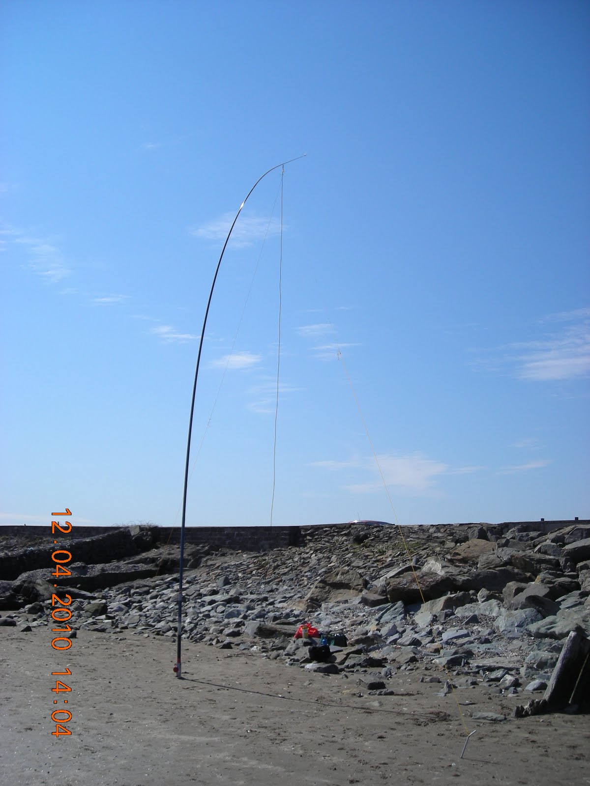
I also managed some /P operation from the rally as MI1KTA/P into a 20m dipole and then on the trip back on two afternoons from the beach near Dublin as EI/M1KTA/P and managed several 2xqrp contacts. Worked qrp DX included RA1CW and 4X4FR.


Monday, 5 April 2010
Loch Erne (Enniskillen) Rally 11th April

Just getting the display of kits ready.
Cannot bring the whole shack so in the box will be (everything I have soldered from kits):
The web links are current and provide info on them, some not from vendor.
HB-1A / Direct from BD4RG http://k1hah.net/HB-1A-MK-II.html
PFR-3 / http://www.qrpkits.com/pfr3.html
ATS-3B / KD1JV http://kd1jv.qrpradio.com/ATS3B/ats3b.HTM
MKARS80 & CW Adapter /G6ALU http://www.radio-kits.co.uk/mkars80page.html
BITX20A / http://www.qrpkits.com/bitx20a.html
Softrock -40 (yes the one that started the SDR craze off) / AmQRP & KB9YIG http://www.amqrp.org/kits/softrock40/
FCC-1 & FCC-2 Frequency Counter and DDS / Norcal http://www.norcalqrp.org/fcc1.htm http://www.norcalqrp.org/fcc2mkii.htm
Si570 USB DDS / G0BBL http://www.sdr-kits.net/USB/USB_Description.html
A simple keyer / ??
Tenna Dipper / KD1JV http://www.4sqrp.com/kits/td/td.htm
SLT Tuner / http://www.qrpkits.com/sltplus.html the new version
BLT Tuner / G3RJV but look here http://www.qrpkits.com/blt_plus.html
FUCHS Antenna (OK so this one I built off schematic!) / qrpproject.de
Softrock V6.2 Lite 20m /KB9YIG http://www.wb5rvz.com/sdr/New_SR_Lite/
FDIM2008 11W PA Buildathon - FDIM 2008 Proceedings.
10W PA / W8DIZ http://www.kitsandparts.com/linearamp.php
Digital Dial / http://www.qrpkits.com/freqcounter.html & KD1JV
For the SDR display will have:
Softrock V9.0 With electronic BPF
Softrock Ensemble RXTX
I might have a V6.2 & V6.3 RXTX.
I will have a few KB9YIG unmade kits for sale with me if interested.
Sunday, 4 April 2010
EnsembleTRX with HB9DRV SDR-Radio Beta
Just finished building and here is a short video of it working.
EnsembleTRX PA


The final stage of construction.
I built this for 80m and 40m and T3 and T4 are small and the windings tight.
In both cases the bifilar Secondary(T3) and the bifilar Primary (T4) are wound first with the single wire winding being added last. You may find this a little easier.
Now usually if this were a V6.2 or V6.3 I would have added a drop of heat sink compound to the PA transistors before adding the heatsink but a plastic TO220 washer was included so I used that.
The 2N2222A TO18 heatsink is removed in this photo.

I will run a few quick tests and then clean up the boards.
Until I do as asked for them here are some high resolution pictures of the completed boards.
With no flash:

Flash:

Underside:

EnsembleTRX TX Mixer (QSE)


This is 1 SMT Ic and 4 SMT C underneath and on top an additional transformer (T2) and inductor (L1), 9 resistors, 3 C and a couple transistors.
I had to substitute in for one of the 220pF caps (C21)
EnsembleTRX TX Op Amps
Top

Bottom

The TX op amps are two identical sets of components for the I & Q channels to create 0,90,180amd 270 degree inputs to the TX mixer, fed from a single 3.5mm stereo socket.

Bottom

The TX op amps are two identical sets of components for the I & Q channels to create 0,90,180amd 270 degree inputs to the TX mixer, fed from a single 3.5mm stereo socket.
EnsembleTRX PTT switching and RX circuit

OK this caused me a few headaches as one BS170 was duff and so the PTT from the AVR USB was not functioning.
So I replaced the Q10 BS170 and it is now functioning fine. Lesson in there for anyone building one... watch the BS170!

Now to place the RX OP amps (actually just one IC but dual OP amps) already placed the RX mixer FST3253.


That is the RX side complete.
Now to test it.
Saturday, 3 April 2010
EnsembleTRX PTT
OK PTT... managed to get it worked out using Rocky... using cw mode (feel like an idiot as had tried using SSB!) Anyway on PTT in Rocky I get 5V on pin3 of the AVR. Good so far.
With no PTT enabled on the galvanically isolated RF side at the opto output with R36 and R34 in place to tap into the 13.8V line I get 10.71V (13.8V supply) at R51, enable PTT and R51 drops to 0.09V. OK that seems fine.
However if I follow the voltage signals from R51 where connects to Q9 I get 8.73V and this drops to 0.09V on PTT, L4 on PTT I get 0V wrt ground PTT or not. C27 on PTT I get 0.27V on PTT and 0V PTT off. On RX I get zero connectivity through Q10 to the antenna and same on TX.
I suspect this means Q10 is fried?
As it stands on U10 the voltages when PTT is off are:
1 0V
2 2.45V
7 2.48V
8 0V
9 2.49V
15 0V
16 4.99V
On PTT 1+ 15 become 0.1V and 0.11V respectively...
Anyone?
Softrock Ensemble TRX Modification to the Si570 output.
Modification needed for the Si570 output.
Tony just let me know CLK+ (pin 4) should be connected via a 0.1uF and not direct to T1.
"...Mike Collins did a design review on the RXTX Ensemble and pointed out the a direct connection to the CLK+ output of the Si570 is not allowed in the manufactures spec of the part. The fix is to cut the trace that connects the CLK+ pin of the Si570 to T1. With the trace cut, a 0.1uF capacitor may be soldered between the CLK+ pad and the T1 via. Care should be exercised to make sure the capacitor does not short to the USB ground plane on that part of the circuit board...."

So I modified the build.
Cut a track and stripped away the surrounding PCB and soldered a 0.1uF across the gap. Ugly but it works.

This short video shows the output still fine.
Homebrew Bench Video
Been asked if I have a home brew bench video.... so connected up a cheap web cam I had lying about and just pointed it at the home brew bench. This is just me tinning a new iron tip.
Friday, 2 April 2010
Softrock Ensemble TRX Beta Build Divider
Now the LO has been tested as working as reported in previous blog posts (I have not uploaded a video yet showing the LO frequency tests, but I will.. it does work!)
Now to build and test the dividers.
As per Robby's website:

On top just two resistors added to connect to bias the offset into the divider. So the mid point signal is 50% the VCC of U5.

The Divider is tested by looking at a few things:
Check the voltage divider network across those two resistors is at 50% either side.
I get 4.99V mav and 2.49V at half way so that is right. You measure these at the hairpin bends of the two resistors R13 and R14.
Grabbing some food... back after eaten.
Now to build and test the dividers.
As per Robby's website:
The Dividers stage takes in the local oscillator's signal and divides it by 4, producing two output signals. Each output signal is at a frequency that is ¼ the stage's input signal and is a square wave with 50% duty cycle. The 50% duty cycle is with respect to the regular 5V rail.
The signals are "in quadrature", that is, they are 90° out of phase with each other. These are provided to the TX and RX mixer stages as clocking signals. They are called out on testpoints marked "QSD Clk (1 or 2)", for the I and Q signals to mix down the incoming "chunk" of RF, and "QSE Clk (1 or 2)", for the I and Q signals which mix up the PC's line out signals.
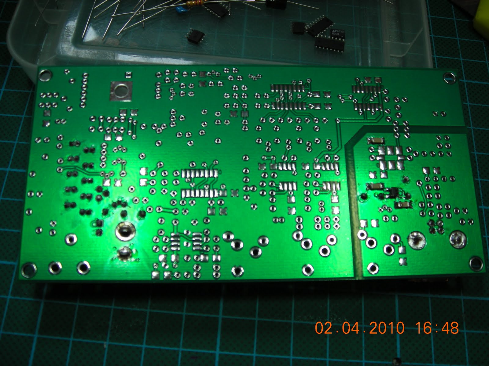
On the underside two components the 74AC74 IC (U5), one decoupling capacitor
On top just two resistors added to connect to bias the offset into the divider. So the mid point signal is 50% the VCC of U5.

The Divider is tested by looking at a few things:
Check the voltage divider network across those two resistors is at 50% either side.
I get 4.99V mav and 2.49V at half way so that is right. You measure these at the hairpin bends of the two resistors R13 and R14.
Grabbing some food... back after eaten.
Softrock Ensemble TRX Beta Build LO test
Now the LO is built have to test it.
Download and install SDR programs and Dynamic Link Libraries, along with hardware drivers. The actual steps anyone else might follow will vary, depending upon the operating system etc.
PE0FKO (Fred) CFGSR Configure/Control Ensemble microcontroller software
PE0FKO (Fred) SRDLL dll for Softrock controllers
The USB driver(s) for the ATTiny85 AVR/USB
(Apologies Fred should have been PE0FKO not PA0FKO as I wrote before)
If you plug in the Ensemble TRX it will (or should) immediately ask you for the drivers to be installed.
Once they are installed the system management console should have an entry for the libusb device like this.


Once the drivers are installed you can test the hardware
PE0FKO software will configure the Softrock USB/AVR/Si570 interface


The current SDR-Radio build I test the connectivity and it will select the USB/Si570 and connect to it and run it.


Soldering Si570 to softrock boards
I took this to explain how to solder the Si570 chip in place.
The 8 pins 6 are large 2 are tiny.
The tiny pads getting these wrong causes about 99.99% of the problems with the Si570 not working as expected.
The 8 pins 6 are large 2 are tiny.
The tiny pads getting these wrong causes about 99.99% of the problems with the Si570 not working as expected.
Softrock Ensemble TRX Beta Build
I started this here:
http://m1kta-qrp.blogspot.com/2010/03/new-sdr-trx-from-tony-parks-beta-build.html
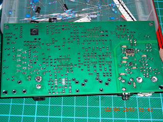
Anyway here are some photos: (BTW the boards will look terrible as I have not cleaned them up removing all the flux etc)
The reverse is of the pcb was not silk screened so here I ID the components

First thing build the power supplies.
The 5V one is easy and uses all through hole (top surface) components so I didn't take a photo of it separately. The 3.3V supply from the USB socket is a different matter though as that regulator chip is tiny:

Anyway this is what the board looks like top side with both supplies in place.

And same thing from underneath.

I ran tests on the voltages in and out and believe me that the 5V (I get 4.99V) is fine. The USB one (I get 3.31V)

Adding the LO / sI570
I have had more than a few questions about soldering the Si570. This post I explain how I solder mine in place. Apologies about the 'um err'ing in it.
Once done this is what you get the top right pad is soldered all others not and chip in place and lined up.

The board after the whole LO is built top side

bottom
http://m1kta-qrp.blogspot.com/2010/03/new-sdr-trx-from-tony-parks-beta-build.html
Anyway here are some photos: (BTW the boards will look terrible as I have not cleaned them up removing all the flux etc)
The reverse is of the pcb was not silk screened so here I ID the components

First thing build the power supplies.
The 5V one is easy and uses all through hole (top surface) components so I didn't take a photo of it separately. The 3.3V supply from the USB socket is a different matter though as that regulator chip is tiny:

Anyway this is what the board looks like top side with both supplies in place.

And same thing from underneath.
I ran tests on the voltages in and out and believe me that the 5V (I get 4.99V) is fine. The USB one (I get 3.31V)

Adding the LO / sI570
I have had more than a few questions about soldering the Si570. This post I explain how I solder mine in place. Apologies about the 'um err'ing in it.
Once done this is what you get the top right pad is soldered all others not and chip in place and lined up.

The board after the whole LO is built top side

bottom

Subscribe to:
Posts (Atom)


