


Built the rig and got it up and running fine, then the LCD went out and all the 5V rail is dead.
Seems I have a short somewhere, don't appear to be a duff components so must be a bridge under IC 5, 8 or the DDS chip.
Nice suggestion from N1RX (Bruce)... cut the 5V rail isolating the IC/board area and find the bridge.
Saturday, 31 October 2009
Thursday, 29 October 2009
HB-1A kit build - part II
More photos from build last night.
The connections and components to test the DC

The switch postion to test DC.

The IF chain, dial 602 and lm386

The DDS through a magnifying lense... bit blurred

The dds as seem naked eye. Think I did ok soldering that by eye but needed to reflow pins 13,14 and 15.

Now put into a PCB vice http://www.qrpkits.com/ and populating the board with through hole components

Top side more components.
Note I changed the kit supplied IC sockets for turned pin sockets as I suspect will remove the IC onces or twice in future

HB-1A kit build

All ready for the start. 0.1uF and 0.01uF SMT first.

Small 0805 SMT components
Various stages through the population of the boards:


soldering is fine but not perfect, I worked with naked eye, 22SWG
multi core solder, temp controlled iron and 1mm bit and hand soldered,
so it is possible. I even managed the DDS chip without having to flood
and wick excess away… it is on a degree or two little wonky but fine
otherwise. I used a pinch to release type of tweezers you can see on
one of the photos to pick up components. The R and C are all 0805
which is big enough to be hand soldered but small enough to probably
cause some a few issues. Once the SMT R and C were in place and tested
the DC lines I tranfered to using a PCB vice (www.qrpkits.com)
Early in the process I added the main switch S1 and the DC supply
socket, fed with 13.8V and sensed the 6V and 5V pads around the board
feeding the IC's. My 5V is 4.996V and 6V is 6.035V. The voltage values
I get on different pins are within 5% of Bruces so I'll not reproduce
them here.
Anyway I have added photos to the hb-1a yahoo group M1KTA album for
those interested but I attached them here too.
The timestamps on the photos are accurate so you get an idea how long
it should/could take. I expect to complete this later today.
I will say that I was missing a few SMT components (R 2K2 and 47K
which I robbed from the junk box) but I was sent heaps of extra other
values and a pair of 602 and a 386… so I know what I'm building next…
another IF chain.
Maybe a 2x hb-1a homebrew build qso might be possible if anyone
interested, I am in UK and cw is qrs!
Tuesday, 27 October 2009
GQRP 2009, that B2set and Paraset
Ian (G3ROO) said... take a look at what I brought for the show and tell at dinner the evening before the GQRP rally....

Johnny SM7UCZ did the same and handed me a paraset!

Photos of the psu Ian (G3ROO) had built so that his rebuild of a B2set would be operational for the GQRP rally. His original transformer is being rewound as some of it has gone open circuit.


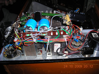
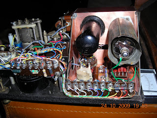
The underside of the TX side. Ian G3ROO, just as I am, has built his set to use so some accomodations will be made in this case Ian has used torroids to create the fixed values for the tuning circuit rather than 1/2" paxolin/tufnel coils as in the original. Likewise ALL the wire looms are using PVC coated modern wire.

The chokes were some I had left over from a box I shared with paraset builders.
Note the chassis was made using some double sided PCB rather than the original steel but to the original dimensions.
 The tune side capacitor is not original as they are rare but the value is the same, as Ian luckly had a part T to start with the load side capacitor is original.
Some photos of the wiring loom, again accomodation using modern R and C's so that the end result is usable.


The TX side access to the small orange 4-20pF trimmer capacitor

Top view of the TX side.

Ian tells me that the rotary switch is functional but not original.

Johnny SM7UCZ did the same and handed me a paraset!

Photos of the psu Ian (G3ROO) had built so that his rebuild of a B2set would be operational for the GQRP rally. His original transformer is being rewound as some of it has gone open circuit.


The underside of the TX side. Ian G3ROO, just as I am, has built his set to use so some accomodations will be made in this case Ian has used torroids to create the fixed values for the tuning circuit rather than 1/2" paxolin/tufnel coils as in the original. Likewise ALL the wire looms are using PVC coated modern wire.

The chokes were some I had left over from a box I shared with paraset builders.
Note the chassis was made using some double sided PCB rather than the original steel but to the original dimensions.
 The tune side capacitor is not original as they are rare but the value is the same, as Ian luckly had a part T to start with the load side capacitor is original.
Some photos of the wiring loom, again accomodation using modern R and C's so that the end result is usable.


The TX side access to the small orange 4-20pF trimmer capacitor

Top view of the TX side.

The underneath of the TX

Ian tells me that the rotary switch is functional but not original.
More HB-1A kit photos
The blank PCB
Top side

Bottom

The through hole components spread out.

Starting to place topside components to check fitting etc.
I just updated http://hb-1a.golonka.se/doku.php?id=component_list with some component values.
Top side

Bottom

The through hole components spread out.

Starting to place topside components to check fitting etc.

I just updated http://hb-1a.golonka.se/doku.php?id=component_list with some component values.
HB-1A kit the mysterious R47
R47...For those asking what??? and have a kit, it is on left hand edge (SMT side) to right a little higher than T2. The smt version uses a through hole 2N7000 forQ4, maybe if it fails easier to replace a through hole version? Anyway the centre pin (G) goes to R45, the bottom pin (S) goes to Q1 base, top pin (D) goesto C1... between them there is a R47 that connects the pin to ground...It is not on the schematic. On a built version... (thanks Roy) it is marked 103.
Monday, 26 October 2009
Rishworth 2009 Homebrew Build
The display had everything from cutting edge smt to 1940's valves with the only requirement being that the components had to be be soldered in by a builder. I think everything was qrp! Absolutely everything from full blown kits to ugly style constructions were displayed. I brought my first ever (working!) valve radio a 6V6 TX from the GQRP valve day in July.


along with a selection of random builds inclding a MARS 80m (Sprat #140) build that I only started populating on Thursday. Next to it on the left is Steve KD1JV ADC-40 rig.

and although cut off in the photo is the PCB from the HB-1A kit I was just sent from China.
Roy GM4VKI added his built HB-1A to show how it will look after building it.
Ian G3ROO also added an all valve RX and George G3RJV brought something he had been sent in by a JA.

Here are some images from the Homebrew Build display area before everyone arrived:

Ian (G3ROO), Dom (M1KTA) and Roy (GM4VKI), ?? (sorry!) discussing the projects over pie and peas before the doors to the area opened.

Steve (G0FUW) and George (G3RJV) had not set up the Buildathon places at this point.
Steve (G0XAR) and Hans (G0UPL) added their QRSS T and Class E >85% efficiency PA's.
After his talk Ron G4GXO added his T2 and Si570 dds to the display and John G4EDX bought his ugly Norcal 40 and an MFJ like analyser, the latter generating a lot of interest probably as it being being painted fluroescent pink!
There were a number of other projects added during the day including a Pic-A-Star by Rod G3

Here are some images from the Homebrew Build display area before everyone arrived:
Ian (G3ROO), Dom (M1KTA) and Roy (GM4VKI), ?? (sorry!) discussing the projects over pie and peas before the doors to the area opened.

Steve (G0FUW) and George (G3RJV) had not set up the Buildathon places at this point.
Steve (G0XAR) and Hans (G0UPL) added their QRSS T and Class E >85% efficiency PA's.

After his talk Ron G4GXO added his T2 and Si570 dds to the display and John G4EDX bought his ugly Norcal 40 and an MFJ like analyser, the latter generating a lot of interest probably as it being being painted fluroescent pink!
There were a number of other projects added during the day including a Pic-A-Star by Rod G3


and Johnny SM7 added his paraset.
Thursday, 22 October 2009
Wednesday, 21 October 2009
HB-1A SMD kit this is what you get.
The shipment had taken just over a week and, there was no customs charge, VAT or extra handling charge to pay, so the radio cost me a total of £137.82. There was a delay in arrival that was 100% due to time spent in the UK Coventry Customs arrivals point but then I expect a couple extra days ude to bottlenecks I have experienced for shipments coming from there in the past. It took 5 days real time to get to my door but an additional 4 days spent in customs!
Opening the box revealed the radio extremely well packed in expanded polystyrene, plus a photo-printed card with a picture of BG2FX in his lab - presumably the builder. There was no manual, but the eBay listing had linked to an English language manual in PDF form that I could print out.
This is a short video to show you what you get.
The PCB has the surface mount all on one side and in this video I show you the board.
I also show the components in this video.
In the video I say the case is Aluminium... the case is steel! I noted that the bag is not anti static and the PIC and semiconductors are NOT pressed into foam etc. I expect I will check those first!
The clam shell steel case (palm paddle magnet will attach to it) is pre drilled well-painted in a black crackle finish. The white lettering is adequate although I do not think it may last too long.weight.
GQRP Rally Homebrew Contest/Display
Back in SPRAT #139 there was an announcement that there would be a homebrew display/contest and Graham/George were looking for volunteers to help. Well I volunteered....
I posted to the list too but just in case put it on the blog too.
Please if anyone thinking of bringing something along, and there are no categories at all this year it is completely open so you could almost bring anything, please contact me off list (UNTIL 10am FRIDAYwhen travelling up to Rishworth) or on the day at Rishworth. If you can though please bring a A4 sheet showing the circuit or description and your callsign and what you call it. I am sure those looking at the builds might want to ask the builder the odd question too.
I will I have my nth build of a 6V6 valve rig I finally got working thanks to many donors of bits and used on 80m in GQRP valve day this July.
George's comment to me this morning was "We think it will be in theBuildathon area .......still got to work out space and oversight. I suspect we will put things in the room early then allow the public inonly when the Buildathon begins [12.30]". This means the display area should not be left unattended.
Following the list kit thread I thought I'll bring somebuilds/projects to display. PFR-3, ATS-3B, an ATS-3 Unbuilt, QBSA,NorCal-20, BITX20A, KD1JV MARS (#140 SPRAT rig), KD1JV ADC-40 andKD1JV PSK and K1SWL PSK-20, my own pcb versions of VK3XU (DrewDiamond) TCF 40 Manhatten/Paddy Board RX and TX boards, Norcal FCC-1/FCC-2 frequency counter/DDS, qrpkits BLT, qrpkits long wire tuner, K1SWL SW20+ and anything else suitable that will fit in the box. I may have the HB-1A SMT kit BD4RG just sent me from China...
Anyone able to bring along a K2, K1, KX1, Howes, Tentec or Walford kit, with the cover off?
72
Dom
M1KTA
I'll put up photos and links for the projects that turn up.
Tuesday, 13 October 2009
TR switch for use with a SDR RX and main TCVR

TR SWITCH
After Simon Brown's SDR talk at RSGB Convention this year I have been looking at ways of using a SR with a 'normal rig' and I found this circuit. The eLAD device he mentioned was not available and I couldn't read the circuit diagram. There are probably a zillion ways to do this... and I claim absolutely no originality for the idea/design. This circuit is from a Ten Tec Argosy, and handles that rig's 50 watts with ease and I found it was fine for my use, cw only right now.
The circuit appears broadband enough for HF use, not sure about use up to 6m though. The notes are that this requires 20 to 40 mA of total diode current.
The paralleled 330 ohm resistors. 330 ohms, 1/4 watt may be ommitted if there are no breakthough problems from local AM stations.The IRF510 MOSFET is used as a switch and I think most qrp homebrewers have at least one spare of these. If not try GQRP sales, I also tried it with a IRF630, either way if this doesn't switch very fast then the capacitor (.47 uF a 100V box capacitor from the junk box) that holds the switch closed on TX would need to be larger, I think you can modify the qsk delay at this point. There are probably smaller MOSFETs available for such low-current switching and I think a 2N7000 might even be used? 1N4007's are 1 kV rectifier diodes that I happen to have in the junk box, I also have some MPN3404 and MPN3700 from W8DIZ but the 1N4007 seemed to do fine and I didn't need the PIN diodes. They appear to operate fine. I used 1N4148 instead of the 1N914's and at 5 watts, I have also had satisfactory results with them.
The chokes are small molded ones bit like fat 1/2 resistors.
Monday, 12 October 2009
HB-1A QSK delay
There is a hardware method to extend the qsk delay but I wonder as the keyer is separate from the main control PIC if it might be possible to alter the timing of MUTE signal from pin 6 of the Keyer PIC (12F629) (or the main PIC (16F73) pin RB6) if, and that is the key, no pun intended, the asm became available to do this. That both are F types and not C types means they could be reprogrammed, although in circut programming support does not exist that would mean removal for reprogramming. But both are non SMD devices.
That said as the keyer PIC is separate from the main control PIC and the button S3 (CQ/SET) is used for the CW CQ message I suspect another option might be to roll your own keyer. I wonder if there is enough PCB 'space' to use a small daughter board and say SMD PIC16F628 if so then a lot of the 16F628 keyers out there (code and pin number dependant obviously) might be possible.
Maybe other possible keyer chips might be used?
Softrock V9.0 (with electronically switched BPF)

A Softrock V9.0 RX with isolated antenna input and sound card outputs (using 600 ohm isolation transformers). There is no BPF fitted in this image. The BPF that goes with this build I include a couple of close up images of it, I placed it on a £20 note so you can get an idea about the scale involved. This particular electronically switched BPF is made up for 80m-10m and 6m. The final one Simon has now is for 160m to 10m.


Simon Brown (HB9DRV) of Ham Radio Deluxe fame asked me a while back if I'd help with building a Softrock v9.0 RX for him with an electronically switched BPF. This I did for him prior to the RSGB 2009 Convention where he gave a presentation on his new SDR software using a £50 radio, which is the one that I built for him. The software is so new that today (12th October 2009) he is only 6 weeks into developing it. I provided him with a WAV capture file for him using this very Softrock radio, in the presentation he used the RF Space IQ radio with the 20m beam live and a couple of the prerecorded WAV file including the one I recorded of the SSB segment of 80m during the last RSGB Club Contest 10th September. He now has the radio and has said will be using it to write support for the Softrock and will be adding remote support where he will provide a facility for a console/server situation where the Softrock can be operated remotely and will also have integration with another transceiver with CAT support. So the Softrock SDR can be the fisrt or second RX.
You can follow the new software developments here:
As I mentioned to one or two after the presentation, I had not expected Simon to advise it was me that had built it for him, but I will be happy to build and test one of these for others as I had for Simon at a small charge in addition to the cost of the kit and parts.
These are answers to questions I have had and in the hope I don't get repeats I answer them here as part of the post instead:
I am not developing Simon's SDR software he is.
I do have access to test builds and yes I have a SoftRock V9.0 working with it in my shack.
Although I am in contact with Simon if you have requests about the software ask him not me.
The ONLY source for Softrocks is Tony Parks, himself and THE source for kits is http://www.kb9yig.com/ Yes some others have them but they will utimately get them from him. You will find any supply problems are probably due to availability of suitable Si570 chips.
From time to time I may have some kits that I will build for others but I will never sell an unbuilt kit.
To my knowledge you cannot make/buy a PCB and build it yourself cheaper in ones and twos so buy a kit.
No I do not have the PCB masks, Tony does.
The isolation transformers are 600 ohm 1:1 with a frequency response able to cope with signals above 5KHz without large attenuation. Some cut off at 5KHz that are fine for PSK and digital modes, these were better than that. I cannot recall what they were but cost c£5 each. You can get very very good audio isolation transformers that cost a lot more than that.
The I and Q audio connectors are gold plated and isolated from the chassis.
The RF connector is isolated from the chassis.
The PCB is isolated from the chassis.
The chassis is a dicast Hammond Box.
The main image is for the TOP of the board so you see the C and R and the voltage regulator... you have to look underneath to see the the SMD components. I did not include that image I will later. These were three images Simon Brown (HB9DRV the Ham Radio Deluxe guy) used in his RSGB 2009 Convention talk on SDR and a £50 radio as I built the one in the photos for him.
To answer the question is it difficult to built is not so easy....
The answer is yes and no....I find it easy to build.
What are the challanges:
The BPF toroids are T25 and T30 so they are smaller than most will be used to (T37 or T50), if you can wind a T25 or T30 with SWG 30 wire then those are not a problem. I check the L values with a meter (mine from N6BM.. think I blogged my homebrew build not sure)
The BPF has two SOIC i.e. SMD IC on the base (see images). You can solder the pins using a 'flood' technique where is doesn't matter if you bridge the pins as you wick the excess off with desolder braid (or a length of clean briad from RG213 or RG58 (I never throw old lengths away just in case!). That is the lazy/easy way to do it but the chip 100% must be on the board accurately, so tack two opposite pins first.
The main PCB... top side you should have no problems.
The main PCB bottom... well three SOIC IC and the two large ones are 14 and 16 pin devices the mixer and divider, the 8 pin one is even smaller.
The L and C are all 0603 so small, so you need a steady hand, illumination and a magnifying lens. There is a tiny and I do mean tiny 5 pin regulator chip I don't know if these will be easy enough for everyone or not, I doubt it.
The Si570 chip has no legs and is pad soldered as long as you have a fine soldering iron tip that is clean and fine cored solder and patience and do not take too long/heat the chip or the others up too much should be fine.
Some use spray on flux with SMD components to make it easier to solder.
Some use binocular travelling microscopes.
Some have had sucess with solder paste and heat, never done it myself.
I use a 1mm or 0.5mm soldering iron tip on a temp controlled soldering iron, lots of light, normal flux cored 26swg solder and my own eyes.
I have built a few SMD projects for others.....but it is not a business.
Even more questions overnight, rather than moderate all the comments and respond here are the answers all in one place:
Please note I did not design the Softrock and I make no claim to have done so otherwise, Tony Parks KB9YIG is the designer. If you want to suggest changes contact him, or make them yourself and experiment. After all as I am sure Tony has stated before these are SDR samplers.
Numerous questions about the build
Q: The two electrical components in the picture near the bottom of the box, I assume those are the isolation transformers.
A: Yes, I have a box, literally of these, of various types bought from all sorts of rallies and electronics places. To test them, yes you need to test them! I put a mic on one side and the other connected to a DC-100kHz noise source (some PIC project and scanned the audio frequency. The input feed into an audio spectrum analyser (Google for a free one). I ignored the spec sheets as some are not that accurate. What I was looking for is those that DONT attenuate the frequency until about 25KHz. The ones that do and below are fine for PSK and SSB recording but IMHO crap for SDR, unless you don't mind loosing bits of the ends of the frequency response. The reason you may want/need these is to remove the LO signal, the S9+ big peak in the middle of the SDR frequency spectrum... if it isn't there then don't bother and save yourself the expense. The reason is ground loops are NOT your friend with SDR radios.
Q:How did you mount the isolation transformers to the box? It looks like there two lines of tape involved, any comments?
Q:How did you mount the isolation transformers to the box? It looks like there two lines of tape involved, any comments?
A: Double sided 'elephant strength' tape. Not a brand name just not weak craft rubbish. I think it is the sort that DIY guys use to fix mirrors to bathroom cabinets and wardrobe doors.
Q:The diecast Hammond box, which part number did you use?
Q:The diecast Hammond box, which part number did you use?
A: No idea. Use what fits. I have a 'junk box' of these as a while ago asked what presents were good and I said tins and enclosures and that is what I often get from relatives now! The comment was meant more for it is metal and solid than some specific box. And as those in the presentation will remember Simon wanted something large and not black. You could get away with making one from double sided PCB... in fact sure that is what I did first time.
Q: On the temperature controlled soldering iron, what temperature setting were you using or would you recommend?
Q: On the temperature controlled soldering iron, what temperature setting were you using or would you recommend?
A: I use leaded solder so hot enough to melt the solder. On the small parts up it a bit as you want the time on the component to be short. If never done it before practice on some SOIC-16 pin devices on some junk electronics.
Q:What parts did you use for your antenna connection?
Q:What parts did you use for your antenna connection?
A: Insulated BNC. IS what it says... the chassis does not connect to the RF ground and there is a teflon(?) insulator. The reason is ground loops and the Socftrocks don't like them... they will work but you really want to use a balanced antenna. I would go with insulated 4mm banana plugs to keep costs down. Simon wanted a BNC/SO239.
Q: What parts did you use for your I and Q audio connections? (I realize they were gold plated)
Q: What parts did you use for your I and Q audio connections? (I realize they were gold plated)
A: Any decent phone connector that is insulated from chassis will do. Lots of different options. The ones I used were expensive and used similar teflon insulation, you can buy plates with two phone sockets on the plate is plastic... that would work.
Q:What parts did you use for your chassis isolation standoffs?
Q:What parts did you use for your chassis isolation standoffs?
A: hihi... the Softrock V9.0 comes with them. Look at the corner holes on the PCB, now REALLY look at them, they are insulated from the PCB ground plane... So use the fixings you were sent, I fixed the bolt coming up through the bottom, then the FAT washer, PCB then thin washer then nut.. If does not then sort out something else, you should be able to lift the copper off the pcb corners with a fine blade. Otherwise use a Nyon bolt and nut.
Q:What is the switch for?
Q:What is the switch for?
A:To turn the DC on and off. (too obvious?)
Q:Is the DC connector insulated from chassis?
A:Yes, I used a connector that usually shorts the chassis and barel but when the barrel is inserted it is isolated from chassis.
Q:How long did it take to build?
A:About 2 1/2 hours, including putting it into the box and taking phots for Simon. I had to redo the BPF for Simon swapping band 0 on the BPF back from 6m to 160m on the evening before the presentation and that meant changing the L and C values on band 0 and 1 so thet took an extra 40 minutes.
Q:How did you test it?
A:Follow the DC voltage values, I used an audio spectrum analyser on the isolation transformers, an insulation tester on the connector/chassis connections (the PCB was not in place), you could use a DVM that reads to Mohms to make sure the insulation really is insulated. I measured the BPF L values with a homebrew LC meter N6BM and the frequency response with a VNA. Don't just follow the winding numbers blindly they can be out, check your build! You test the BPF with +5V control signals and check the switching is occuring. Use the USB/Si570 test applications that exist to make sre the LO signals were working and the control signals for the BPF were as expected. (I used a frequency counter and an oscilloscope). Lastly put it on air and made sure it worked.
Q:Where is all the software available for the USB/AVR/Si570 used with the Softrock
A:See http://www.kb9yig.com/ and http://www.sdr-radio.com/ and http://www.softrockradio.org/ and join http://groups.yahoo.com/group/softrock40/
Q:Will you build one for others / do you sell these
A:Tony Parks sells the kits, in the past I have built softrocks (even as far back as the V4.0) and other rigs for those that cannot do it themselves and would do it again, I enjoy building projects. If you are interested then email me about it (use qrz.com for my contact details).
Thursday, 8 October 2009
S Meter Callibration
Posting more as a place holder really.... the values are for my PIC/AVR project I am listing the 'standard' S meter scale for the ADC.
The values are: S Points, Voltage into 50 ohms, dBm into 50 ohms
S0
0.1uV
-127dBm
S1
0.2uV
-121dBm
S2
0.4uV
-115dBm
S3
0.8uV
-109dBm
S4
1.58uV
-103dBm
S5
3.16uV
-97dBm
S6
6.3uV
-91dBm
S7
12.6uV
-85dBm
S8
25uV
-79dBm
S9
50uV
-73dBm
These values are valid on HF. on VHF, values are 20dB lower e.g. S9 is 5uV or -93dBm. I do not think many commercial transceivers adhere all that closely to this scale.
Wednesday, 7 October 2009
HB-1 A? build using through hole components


Although I am expecting the HB-1A kit to use SMD components here are some images been sent to me and appear to be the same from a Chinese manual for the HB-1A kit. It is for a build using through hole components. See above the SMD one is on the right, it still has some through hole components. Note the little trimmer capacitors with the through PCB adjustments.
.jpg)
.jpg)
Pretty sure this is not based on the same schematic as the SMD HB-1A version but maybe wrong but the PCB are HB-1B and HB1C in the same doc.
Select these images to get a larger scale and run through it along side a schematic to see if you can spot the differences.


Compare with the populated SMD version board.

Subscribe to:
Posts (Atom)


.jpg)