Other than a trip which might get the odd mention I will detail projects I am working on, what I want to be working on and what I have otherwise to report on. I will update the individual projects as they advance. As asked I have started to catalogue the references I have follow the link on the left where you can obtain them too. Want to email me wander over to qrz.com and you'll find my email address there. Also twitter @m1kta_qrp
Monday, 14 June 2010
MOBO V4.3.4 SR V6.3 (Original) preparation
I just build a new SR V6.3 from scratch and added the headers for RX and TX IQ and beefed up the power.
I didn't have a 1N5422 but I have a 1N5408 instead and after a quick test then extended the diode PCB pads a little so not as 'tidy' as the little DO41 drop in replacement.
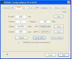
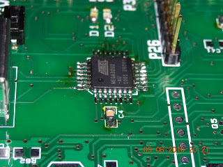
I did a scratch rebuild as the previous build had a LDVS version not a CMOS Si570 in place as a sample chip and could go to >260MHz and as this is for SDR-Radio development I will keep the build to 'vanilla' only.
I noted the MOBO kit seems to have plenty of jumper connectors so will make some up.
I will use a length of RG174 or similar for the RF and I will use some shielded audio cables for the RX & TX IQ.
Sunday, 13 June 2010
MOBO V4.3.4 POWER SWR Head
Images of the build.
I used a length of RG58 as the single turns through the binocular core.
I will also homebrew one of these using 1N5711 and discrete components.
MOBO V4.3.4 PA
I did this:
MOSFET attaches to REAR.
I used a needle file and removed the anodising on the bottom ends of the heatsink and around the TO220 middle mounting hole.
To attach th heatsink to the PCB I used two self threading M3 (ish) screws that bit into the heatsinks and created a good contact (I checked resistance was <0.1ohms). Turned the board up away from you on the right hand side (R30) underneath I used a flat washer and a Computer red insulating washer, on the left hand side I used a flat washer and a star washer that bit into the tinned area. In between the heatsink and the top of the PCB on both sides I placed a star washer.
I secured the heatsink to the PCB first THEN and Only after it was secure did I attach the MOSFET and then checked for conductivity between the ground tab on the MOSFET and GND on he PCB. Once satisfied it was good I soldered the MOSFET into place.
The Heatsink sits about 1/32" off the PCB and it and all mounting hardware is clear of any components..
NB on the (outer edge of PCB) of the TO220 mount I used a brass washer and heat sink compound between the MOSFET and the heatsink, The screw was brass M3. On the reserve side (facing into the PCB) no heat sink compound and I used a star washer and flat brass washer to make a good contact between the MOSFET and the heatsink.
Saturday, 12 June 2010
MOBO V4.3.4 Build for SDR-Radio Support
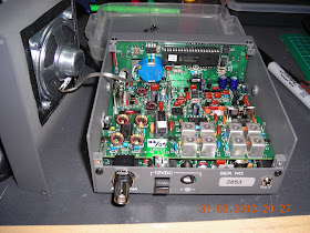
Asked where I am with this so here are the latest images.
About to add the PA.
Then will build the Mini Filters (Set A).
I have a Blue and White 4x20 LCD and a 36 pulse rotary controller. I have a 128 coming from US but not here yet.
Once all together will test and align... then it will be ready for Simon.
Friday, 11 June 2010
Wednesday, 9 June 2010
Saturday, 5 June 2010
Friday, 4 June 2010
IF/AF Strip
I have been building a few things lately all using a 612/xtal/612/lm386 IF/AF strip so I made a PCB layout for it as I ran out of manhatten pads and the expresspcb software was easy to use. I just reworked it and this was done using Wine under Mint Linux (see W8DIZ latest series of QQ articles). If you really need it ask and I can send you the .pcb file, but I never drew designed or made a schematic file and I tend to use pretty wide tracks and spacings as much of the use is with older salvaged components and I found it easier to solder some things that way.